TIDE-1220

New Orleans & Hurricanes

Tulane University

Prof. Stephen A. Nelson

Lessons Learned from Katrina and Reducing Vulnerability
Fall 2014


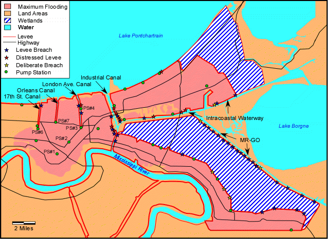
Why did the Levees/Floodwalls Fail During Katrina?

.


Contributing Factors

.

  1. Katrina Storm Surge - increased pressure on bottom of canals & on levees &
    floodwalls

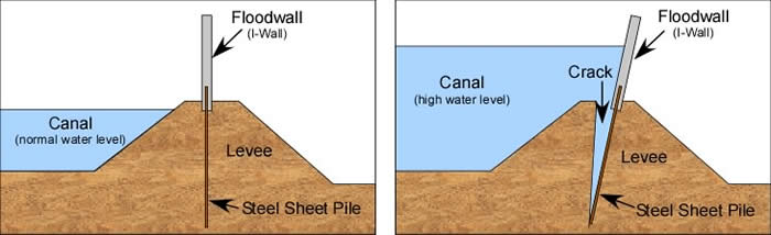
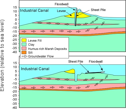
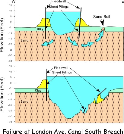
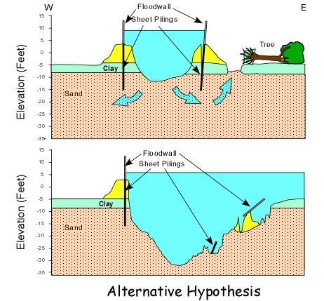
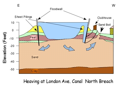
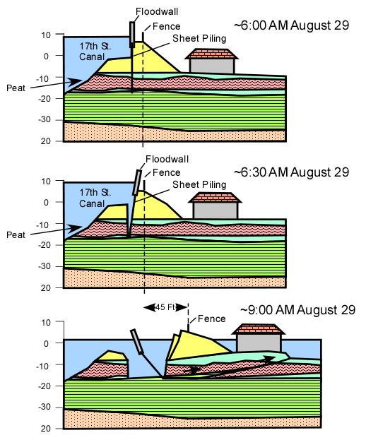
  2. Weak Materials in the foundations of the levees and floodwalls, such as Permeable Sands, Peat, and Weak Clay

  3. Trees uprooted by hurricane force winds

  4. No armoring of tops of levees to prevent erosion after overtopping

  5. Poor design of levees & floodwalls - did not consider all of the above!
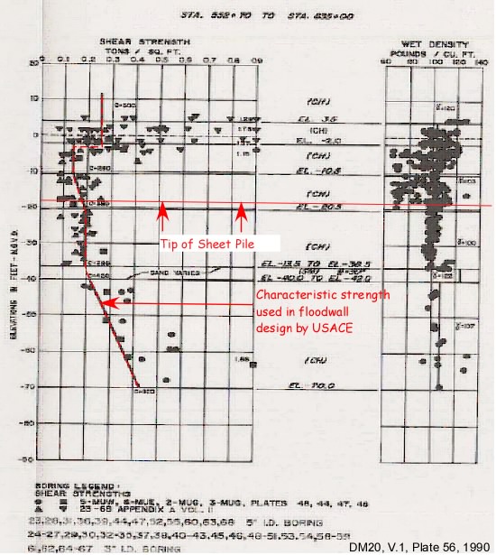
    (I walls instead of T-walls, Low Factor of Safety, Short sheet pilings,
    not enough consideration of complex and variable geological environment)

What could have prevented the failures? - Mitigation of Contributing Factors

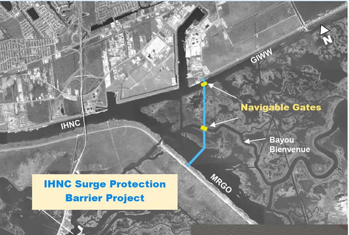
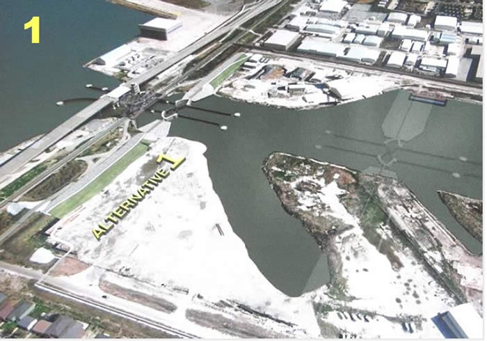
  1. Storm Surge - Keep the Storm Surge Out of the Canals -
    Gates at the mouth of Canals on Lake Pontchartrain
    Pumps at Lake to pump water over Lakefront levees

  2. Weak Materials - Drive sheet pilings deep enough to cut off possible
    seepage to outboard side of canals
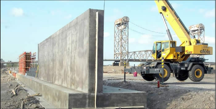
    Use T-walls instead of I-walls


  3. Trees uprooted by hurricane force winds - Don’t allow trees with roots that
    may penetrate levees - remove existing trees

  4. No armoring of levees to prevent erosion after overtopping - Armor tops of
    levees to prevent erosion


  5. Poor design of levees & floodwalls - did not consider all of the above!
    Better oversight of design & construction of protection systems


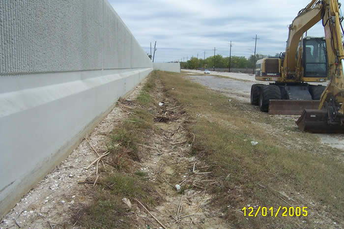
Examples of Problems

Levee overtopping, while it does allow water in to the protected area, is not as serious as levee/floodwall breaching (Figure 1)
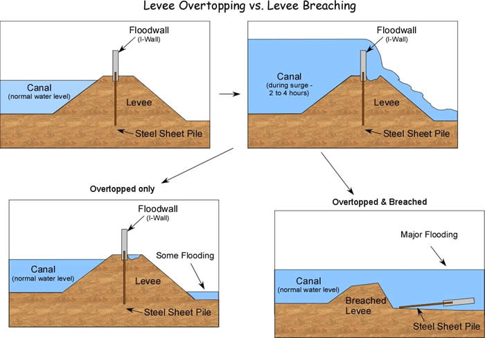
 

Figure 1

During Katrina, Mississippi River - Gulf Outlet (MR_GO) levees  were overtopped resulting in breaching. This resulted in severe flooding in St. Bernard Parish.  The levees were made of easily erodable spoil dredged from the shipping channel.  The levees were not armored to prevent erosion (Figure 2).

Figure 2

In the New Orleans Hurricane Protection System, no armoring was present at the base of floodwalls to prevent erosion if the floodwall was overtopped.

This resulted in erosion of the levees at the base of overtopped floodwalls (Figure 3).

Figure 3

Trench at base of floodwall on Lakefront levee in New Orleans East.

This also contributed to failures along the Industrial Canal (See Figures, 14, 15, 16, 17, & 18 in the Katrina Field Trip Guide - http://www.tulane.edu/~sanelson/Katrina

The other contributing factor in the case of the Industrial Canal levee floodwall failures was a mechanism of I-wall failure discovered after these floodwalls were built.  

In 1985 Army Corps of Engineers research branch conducted tests on sheet pile flood walls with the same design that they were using for New Orleans’ hurricane protection system. Found that they would likely fail! (Figure 4)

Reference:
Jackson, R.B., E99 Sheet Pile Wall Field Load Test Report, Technical Report No. 1, U.S. Army Engineer Division, Lower Mississippi Valley, June 1988, Vicksburg, MS, 83 pp.


Figure 4

The combination of erosion due to the waterfall that resulted from overtopping and the force of the water acting to push the floodwall over, appears to have been largely responsible for the failure of the floodwalls on the east side of the Industrial Canal bordering the Lower 9th Ward (Figure 5)

Figure 5

Failure of the levee on Floodwall on the east side of the London Avenue Canal was due to failure to drive sheet pilings deep enough to cut off underseepage through the sand underlying the canal and levee.  

Figure 6


This failure could also have been initiated by uprooting of a tree by hurricane force winds to initiate the breach (Figure 7).  In either case, the sheet piles were not driven deep enough to prevent the underseepage through the sand.

Figure 7

On the west side of the London Avenue Canal, a similar problem occurred.   But, in this case, the pressure from the rising water seeping under the levee provided enough force to uplift the land in a process called heaving (Figure 8)

Figure 8


At the 17th St. Canal, (see Figures 41 and 42 in the field trip guide -http://www.tulane.edu/~sanelson/Katrina) a sliding mechanism, similar to the failure mechanism discovered by the Corps of Engineers experiments in 1985 (Figure 4) appears to have been the cause of the failure (Figure 9)

Figure 9

In this case the sheet piles were not even driven as deep as the bottom of the canal, but it is also seen that the design failed to take into account the low soil strengths below the levee (Figure 10).  


Figure 10

Shear strength and wet density versus depth along an 1800 foot section of the 17th St. Canal which includes the area of the breach (from U.S. Army Corps of Engineers, 1990, the Design documents for the 17th St. Canal floodwall). The author has added the red lines and red labeling showing the depth to the tip of the sheet piles in the breach zone and the characteristic strength values as a function of depth that the Corps used to determine the stability of the floodwall system.

What Has Been Done or Is Being Done to Fix the Problems?

  • Along the MR-GO levees have been raised to 20 Feet above sea-level and a Standard has been adopted for clay used in levees to ensure that they will not be easily eroded by future storm surge.

  • The MR-GO has been closed to shipping at the Bayou La Loutre Ridge, but this is not a surge barrier!

  • Along the Industrial Canal, the failed I- Wall has been replaced with T-Wall, but only adjacent to the Lower Ninth Ward (Figure 11).

Figure 11

  • Along the rest of the Industrial Canal, concrete splash pads have been placed on top to the levee at the base of the floodwalls to prevent erosion that would be caused by overtopping of the floodwall.

  • All areas along the Industrial Canal remain vulnerable until the 100-year barrier system has been installed (by 2011). Construction started about 6 months ago (Figure 12)
 

Figure 12

(From U.S. Army Corps of Engineers)

  • A gate structure will also be constructed where the Industrial Canal meets Lake Pontchartrain at Seabrook (Figure 13).

Figure 13

(From U.S. Army Corps of Engineers)

  • For the drainage canals, - if water is kept off of the floodwalls, it is unlikely that failures will occur. To accomplish this, closable gates and pumps have been installed near where each drainage canal intersects Lake Pontchartrain.  These gates and pumps underwent tests before and during Hurricanes Gustav and Ike in 2008 - all systems worked!

  • To prevent the possibility of tree blow down tree causing a levee failure, the Army Corps of Engineers has removed all trees within 6 feet of the toe of levees on all drainage canals, despite landowners protests.

What's Next?

The U.S. Army Corps of Engineers has been authorized and funded by Congress to construct a Hurricane Protection System to protect the New Orleans area from the so-called 100 year flood.  

To do so, they needed to determine exactly what the 100 year storm might be.   So the first thing we need to do is explore what is meant by the 100 year storm/flood. and how the effects were determined.   

The IPET task force was charged with determining what the effects of the 100 year flood or storm would be and then to determine the risk to the New Orleans area from future storms.   Next time we will also examine the methodology and results of the IPET risk analysis.


Return to TIDE 1220 Homepage