EENS 212

Petrology

Prof. Stephen A. Nelson

Tulane University

Ternary Phase Diagrams 


In our discussion of ternary phase diagrams, we will first review and then expanding on material covered last semester in Earth Materials on binary and ternary phase diagrams.  You should therefore spend some time reviewing this material.  Links are as follows -

http://www.tulane.edu/~sanelson/eens211/2compphasdiag.html  or for the PDF version -
http://www.tulane.edu/~sanelson/eens211/2compphasdiag.pdf
and
http://www.tulane.edu/~sanelson/eens211/ternaryphdiag.htm or for the PDF version -
http://www.tulane.edu/~sanelson/eens211/ternaryphdiag.pdf

Bring both sets of lecture notes with you to class.  After reviewing this material we will proceed with the following discussion:

When presented with a complex phase diagram, the first thing one must do is understand what phases can coexist during crystallization or melting, and what phases coexist in all possible subsolidus assemblages. Remember that in a ternary system at constant pressure, the maximum number of phases that can coexist is 4, and 4 phases can only exist at ternary invariant points (F= C+1-P, if F=0, C=3, then P = 4). Knowing what phases must be present in the subsolidus assemblage for any composition in the system is important, because it tells us where the crystallization path will lead, i.e. to which of the invariant points in the system where 3 solid phases and a liquid will coexist prior to the disappearance of the liquid phase. Univariant curves, also called cotectics, are lines along which 3 phases coexist at constant pressure (F =1, C=3, so P = 3). Such curves bound the primary phase fields (divariant fields), and by inspection of the phases that exist on either side of the curves, one can tell which phases are crystallizing as the liquid composition moves along the curve. Furthermore, in the absence of isotherms or other temperature information, one can determine the down-temperature direction that a liquid will move along such a curve. The method is as follows:

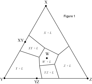
  1. First determine all possible subsolidus assemblages by drawing the compositional triangles. These are also called 3 phase triangles, since a maximum of 3 phases can coexist in a ternary system below the solidus. To do this, examine each of the cotectics and determine what solid phases are in equilibrium along the curve. Next, draw a line between the compositions of the two solid phases that coexist. These lines are called Alkemade Lines. For example, in Figure 1, the curve separating the fields of X+L and XY + L, indicates that X and XY solids coexist along that boundary curve.

An Alkemade line can thus be drawn between X and XY.

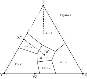
Similarly, the boundary curve between XY+L and W+L indicates that XY and W coexist along that curve, and so an Alkemade Line is drawn between the composition of XY and the composition of W. Also, along the boundary curve separating the fields of W+L from X+L, solid phases X and W are in equilibrium, so an Alkemade Line is drawn between the composition of phase W and the composition of phase X. These three Alkemade Lines are shown in Figure 2, as dotted lines. Note that these lines form a 3 phase triangle and any composition within this triangle must end up with XY, X, and W as the final solid assemblage.

  1. The down-temperature direction along any boundary curve is the direction along the curve that moves away from the Alkemade Lines connecting the two solid phases in equilibrium with the liquid along such a boundary curve. So, for the example in Figure 2, the down temperature direction along the boundary curve where X, XY and Liquid are in equilibrium is the direction away from the XY - X join.

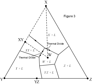
Note that the Alkemade Line for equilibrium between XY and W, crosses the boundary curve where XY, W and Liquid coexist. Thus, the down-temperature direction points toward the bottom of the diagram for all liquids below the XY-W join, and towards the top of the diagram for all liquids on the boundary curve above the XY-W join. This is shown in Figure 3, where the down temperature arrows have been drawn. Note that when the Alkemade Lines for a given assemblage crosses the boundary curve representing equilibrium for the same assemblage + Liquid, that the intersection of the boundary curve and the Alkemade Line is a thermal divide.

  1. Next we want to look at what is actually happening along the boundary curves. In the example shown in Figure 3, the all of the boundary curves with arrows on them are co precipitational. We can tell this from looking at the Alkemade Lines and the arrows. Note that along the boundary curve where XY, X, and Liquid coexist, the back-tangent (up temperature direction) for all liquids precipitating XY and X extends back to the XY-X join, and intersects it between XY and X. This says that the solid assemblage precipitating is a mixture of XY and X. A different set of circumstances is found along the boundary curve separating the fields of Y+L and YZ+L. Note that the back-tangent for any point along this boundary does intersect a line drawn through Y and YZ, but does not intersect that line between Y and YZ. This indicates that the boundary curve is not co precipitational, but rather it is resorptional. That is to say that liquids crystallizing along this join are precipitating YZ, and, at the same time, resorbing Y. The reaction that is taking place is Y + L = YZ. Note that the phase being resorbed is the one farthest away from the intersection of the back-tangent with extension of the Alkemade Line.
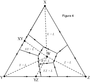
  1. In Figure 4, all of the Alkemade Lines are for this system are shown, and arrows have been drawn on all boundary curves, including the bounding binaries. This has been done by following the principles outlined above.
     
  2. Note that all of the ternary invariant points have arrows pointing toward them. This is the case for all invariant points that are called Eutectics. The reaction that is taking place at a eutectic such as the one where XY, X, and W are in equilibrium with the Liquid could be written as L = X + XY +W.

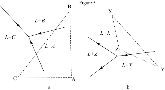
This is not always the case, and other types of invariant points are possible. Examples of the other two types of invariant points are shown in Figure 5. In Figure 5a, note that two arrows point toward the invariant point, and one arrow points away. We say that this type of invariant point is mono-resorptional.

The reaction that takes place in the case shown in Figure 5a is L + A = B + C. As soon as all of the crystals of A have been resorbed, the liquid can continue down the boundary curve away from the invariant point. Only compositions that lie outside of the triangle A-B-C will continue down the boundary curve between L + C and L + B.  All compositions within the triangle A-B-C will become solid at temperatures just below the invariant point.  

Another case is shown in Figure 5b. Here, two arrows point away from the invariant point and one arrow points toward it. This point is a bi-resorptional invariant point. In the case shown, three different reactions are possible, depending on the bulk composition of the material in question. These are:

(1) L + X + Y = Y + Z

(2) L + X + Y = X + Z

(3) L + X + Y = X + Y + Z

For reaction (1) X is completely resorbed and Y is partially resorbed at the invariant point. This would occur for all composition which lie in a compositional triangle that does not include X.

For reaction (2) Y is completely resorbed and X is partially resorbed. This would occur for all compositions which lie in a compositional triangle that does not include Y.

Reaction 3 would occur for all compositions within the compositional triangle, X, Y, and Z. Phases X and Y would both be partially resorbed at the invariant point, and crystallization would cease at Temperatures just below the invariant point, with only solid phases X, Y and Z in equilibrium.


Retrun to EENS 212 Page